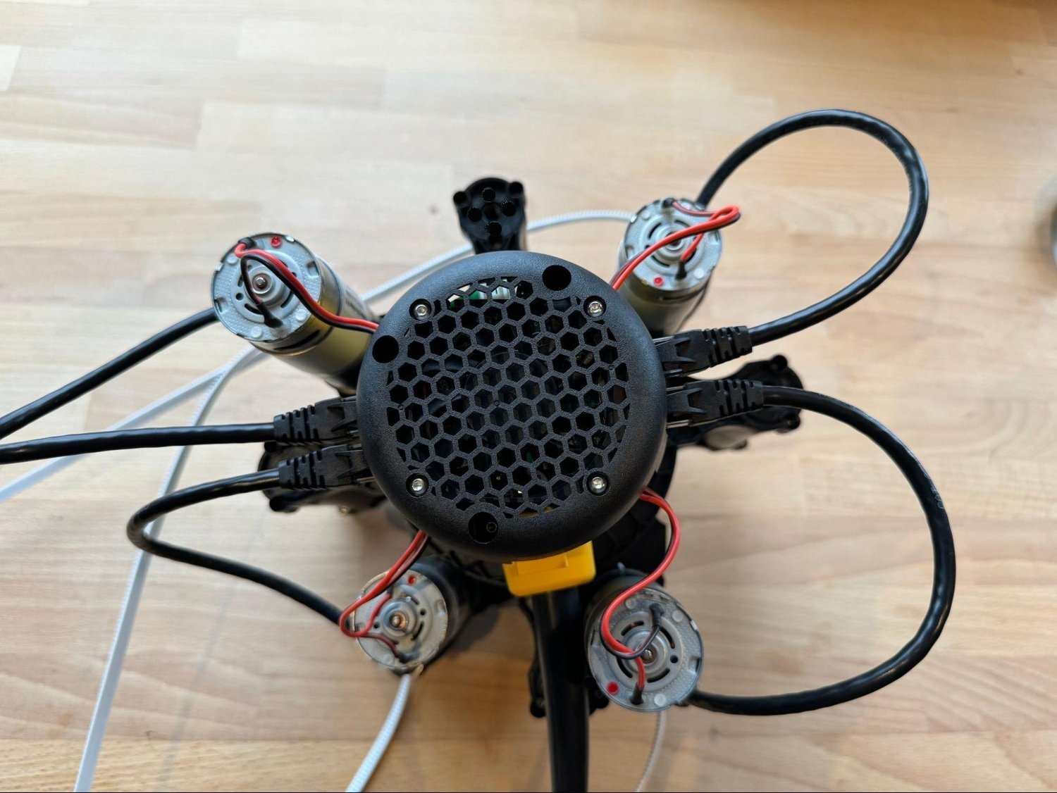
The Dewalt 611 router is the heart of Maslow4. In this step we’re going to attach everything to the router.
A video walkthrough of this process is available here: Maslow 4.1 Router Assembly Video
Find any of these steps confusing or get stuck? Don’t forget, you aren’t alone! Maslow is a community driven open source project. Ask in the forums and we’ll figure it out together!
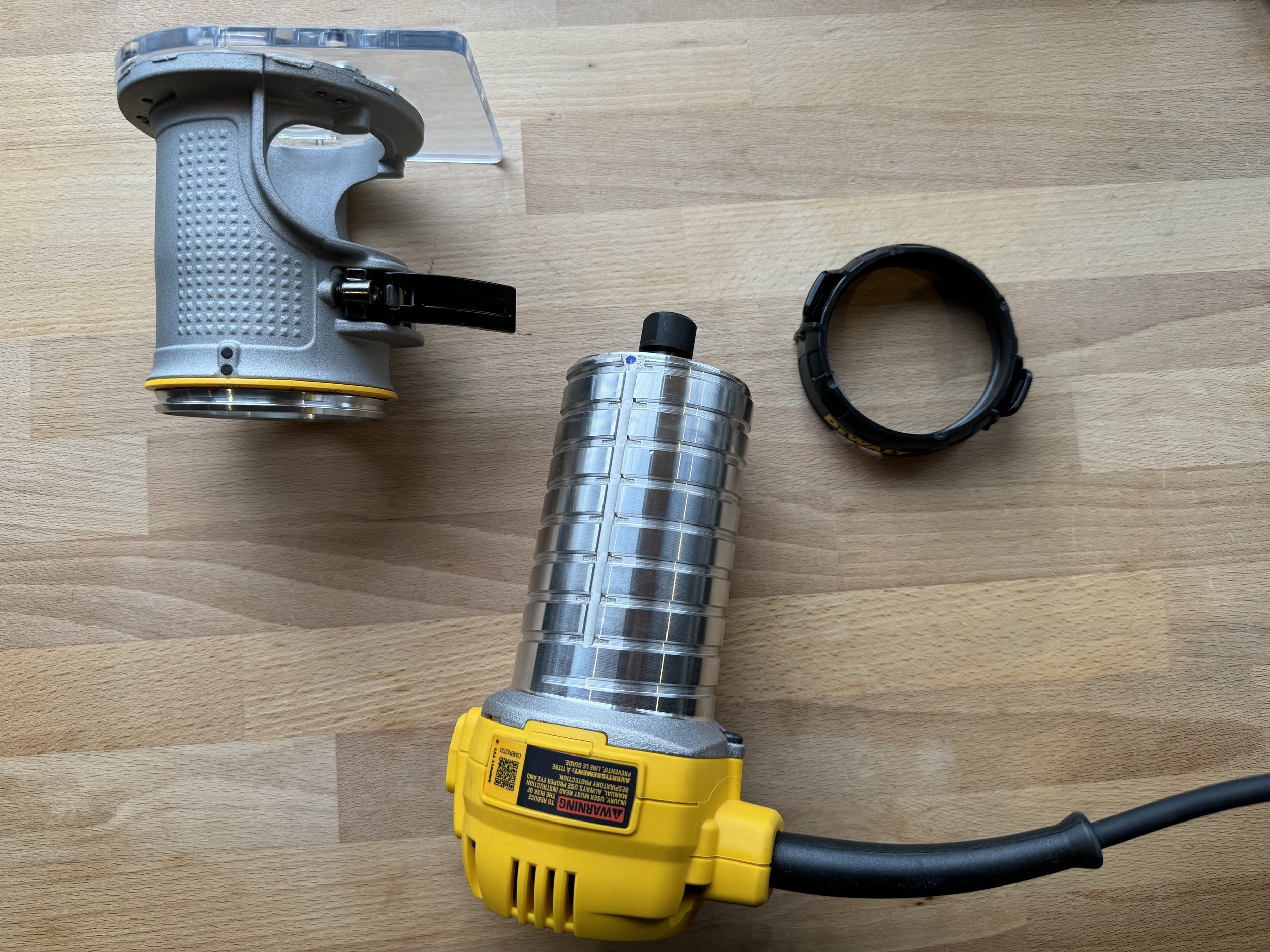
Remove the router body from the router base. Set the base aside, we won’t need it.
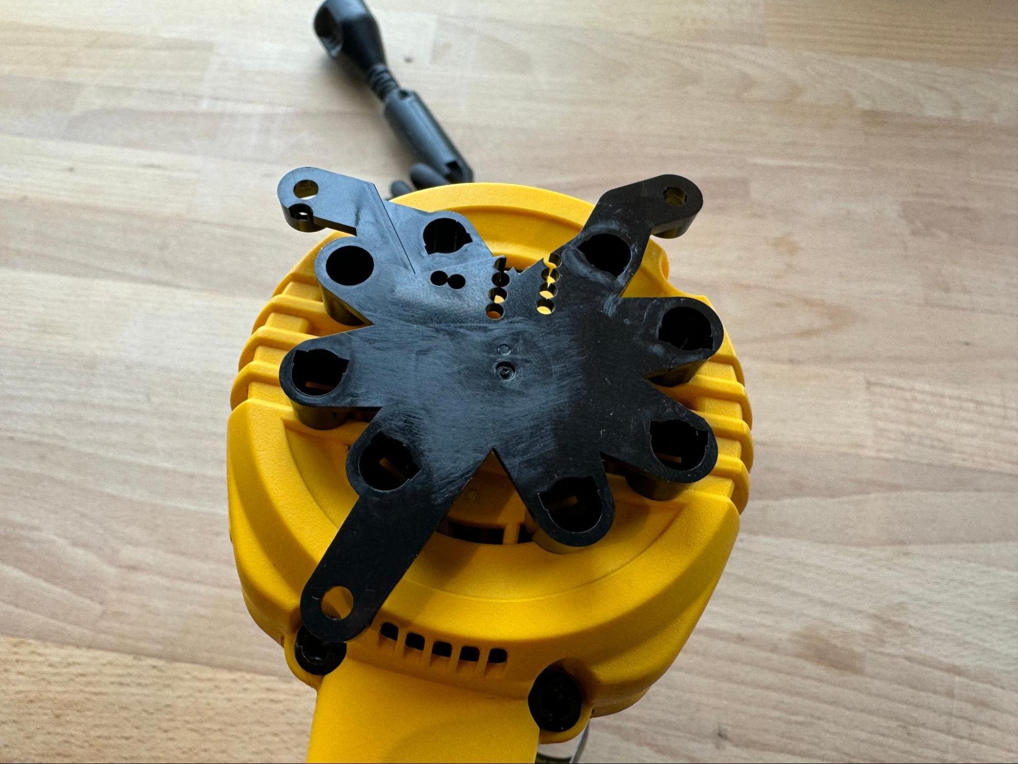
Attach the PCB mounting plate to the top of the router. The orientation of this part is important so be sure that it’s not rotated 180 degrees. The power cord is down in this photo. Use a firm slap or a tap on the table to press it in place.
Note: This part has been reported to fit not quite right on the 240 volt version of the router. See a potential modification to this part here.
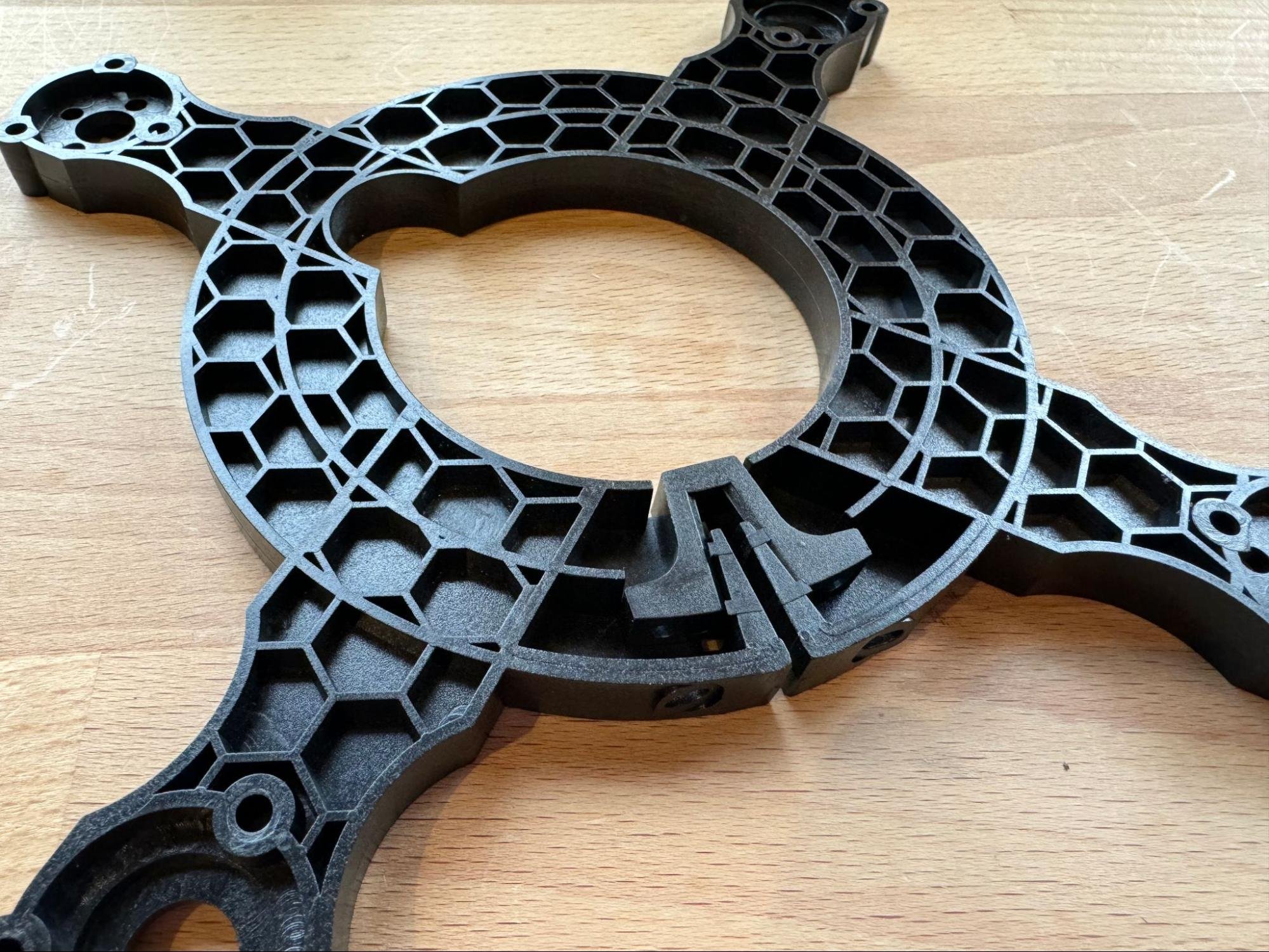
Next find the first router clamp. Note that this is actually two parts together.
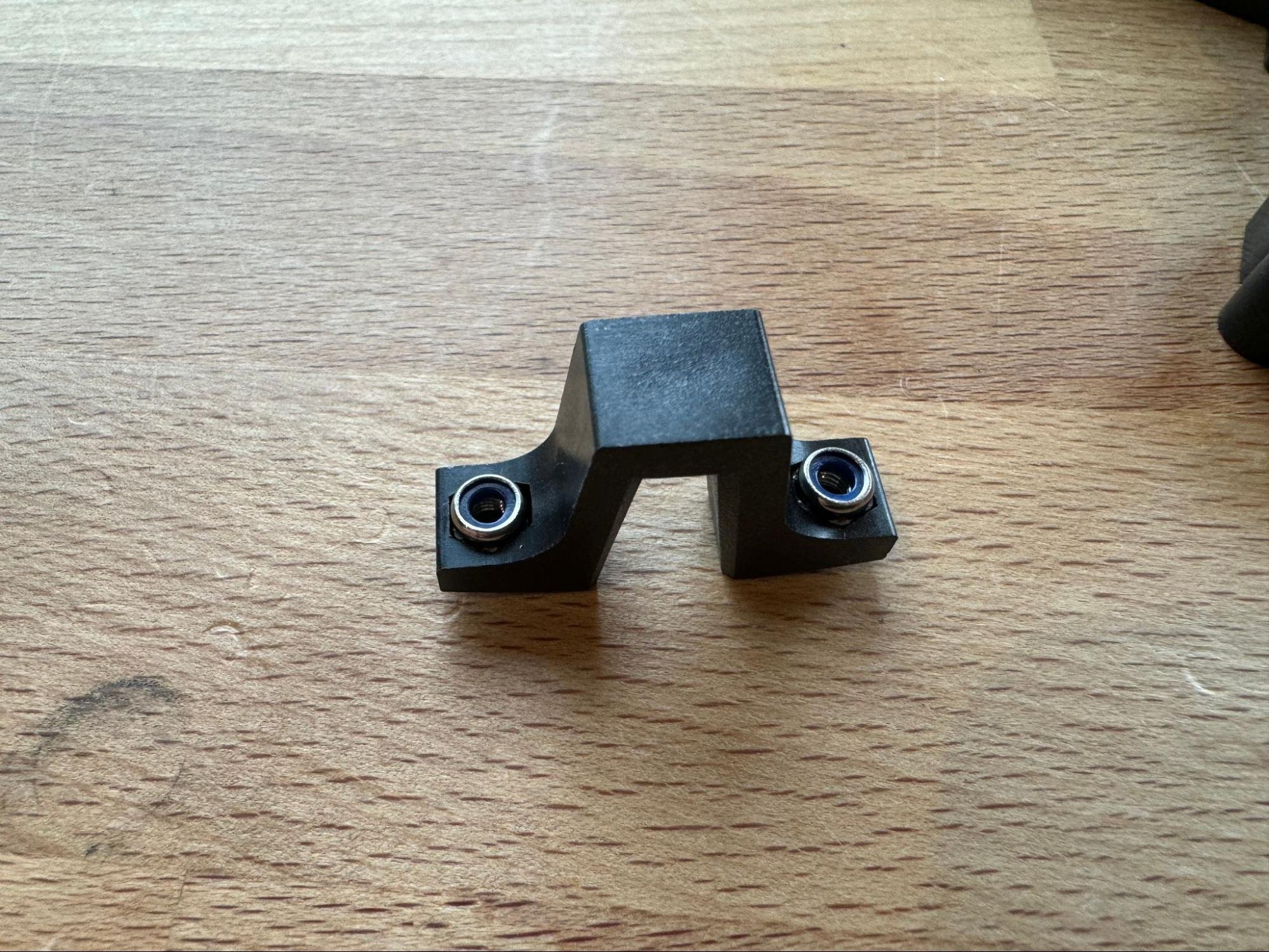
Separate the clamping wedge and insert two lock nuts..
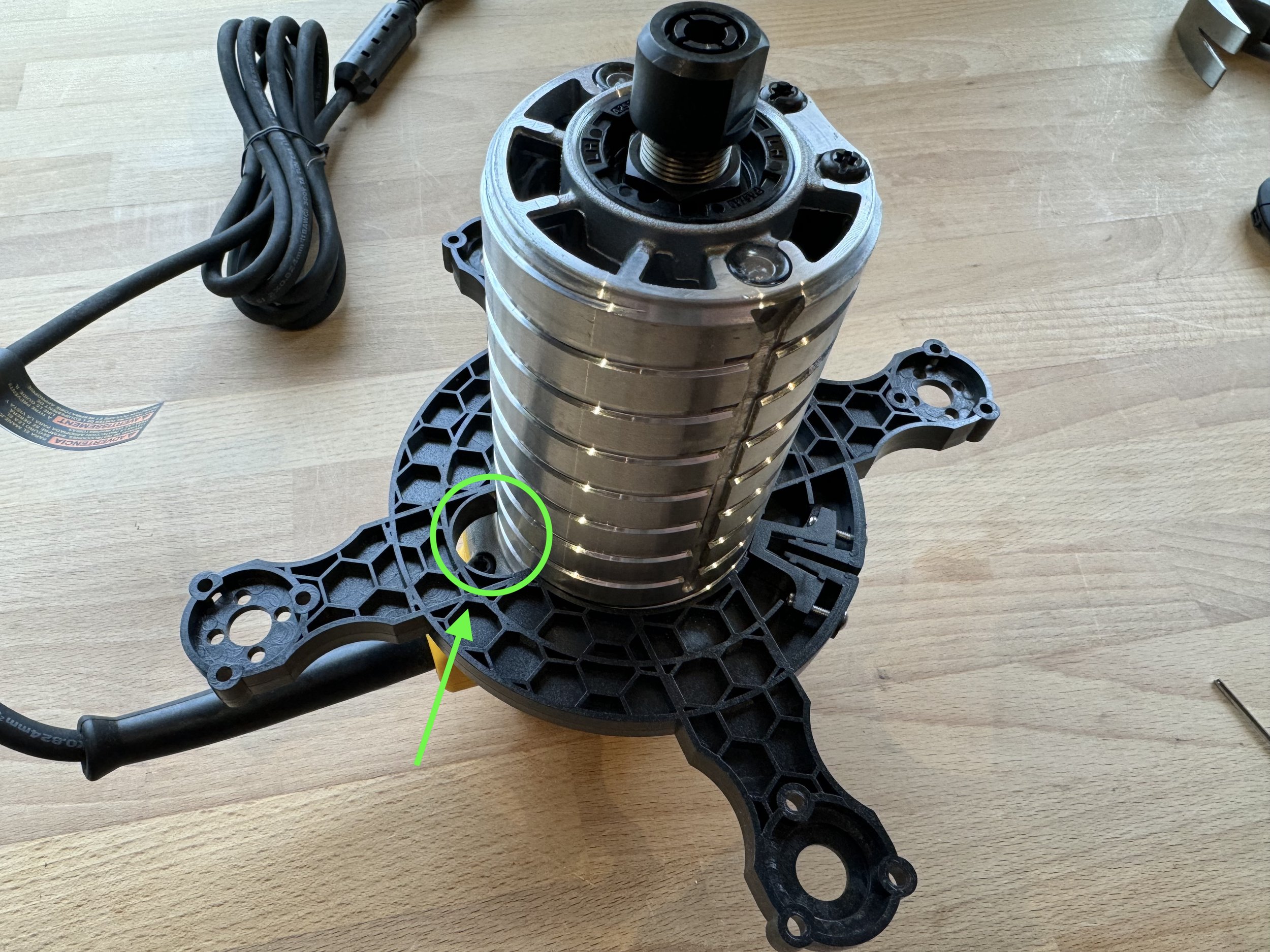
Put the wedge back on the clamp and add two bolts so that they just barely start to engage the threads on the bolt. Then slide the clamp down the router. Note that the notch in the clamp should be towards the power cord.
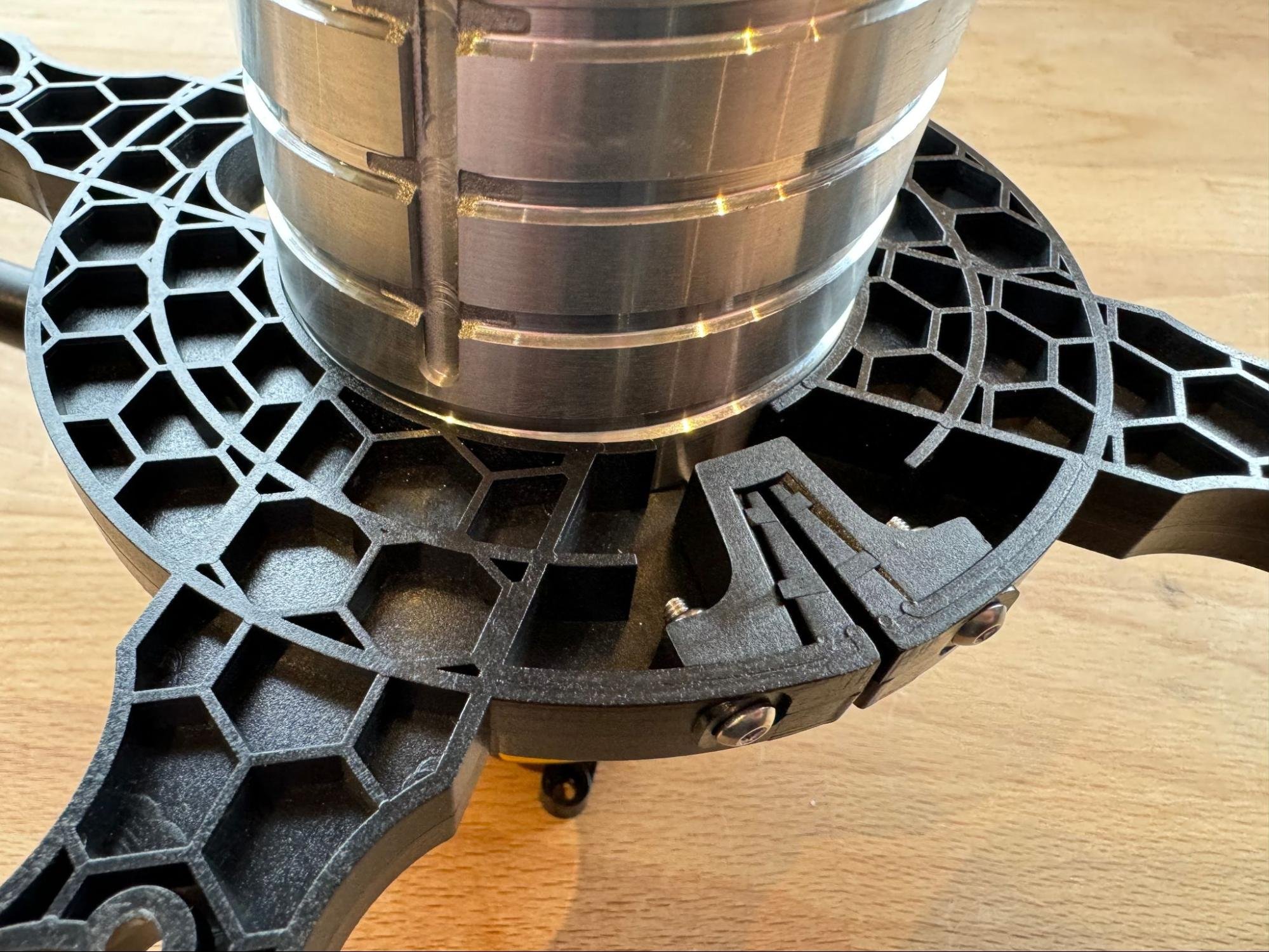
Next, tighten the two bolts to lock the clamp in place.

Next, collect the eight pieces which make up the Maslow4 uprights.
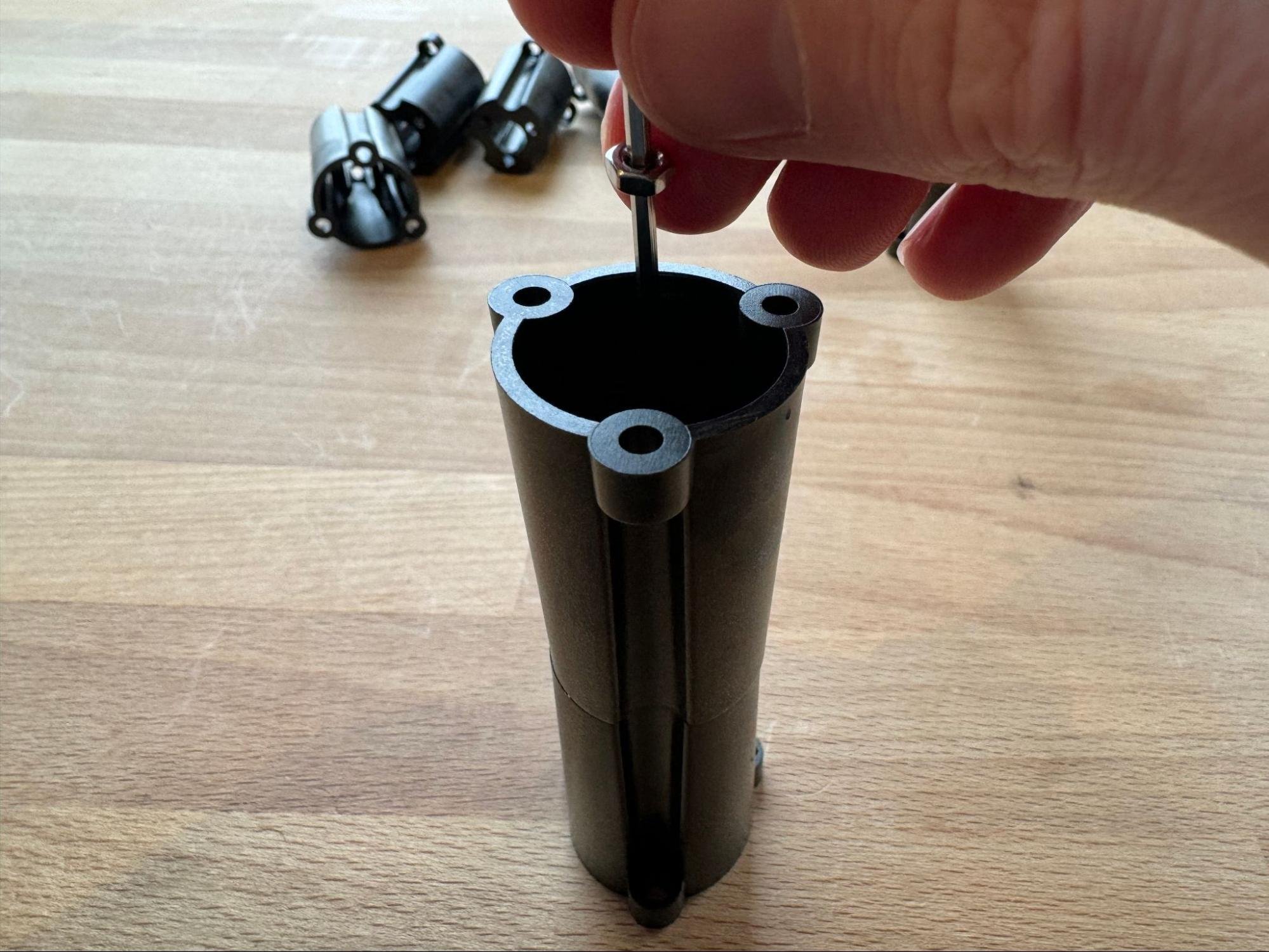
Stack two on top of each-other and then use the Allen wrench to guide a nuts into place in the three recesses at the bottom. I used the regular nuts instead of the lock nuts here because I find it easier.
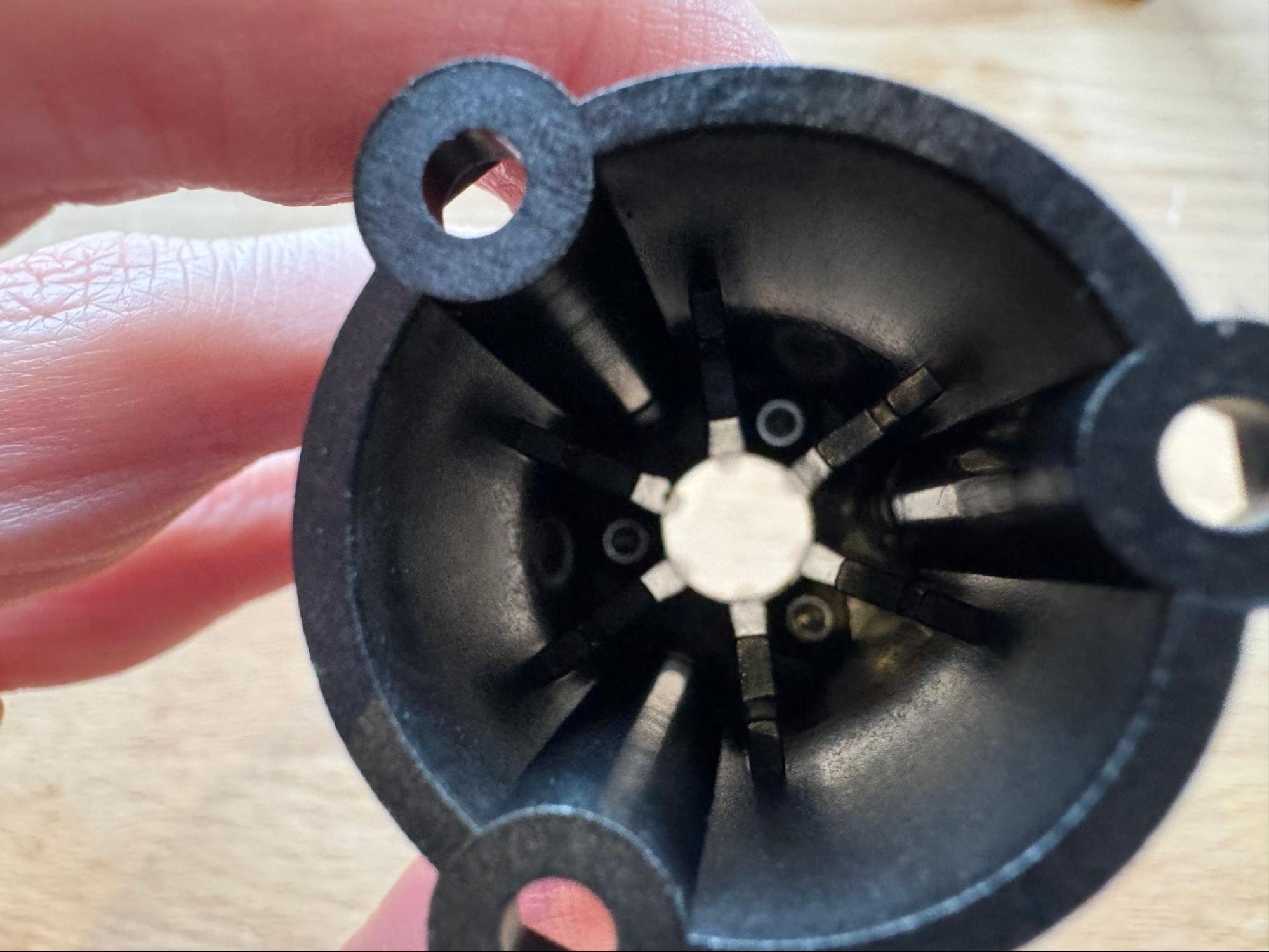
Then add a bolt from the other side. I like to thread the bolts in from the bottom while letting gravity hold the nuts in place.
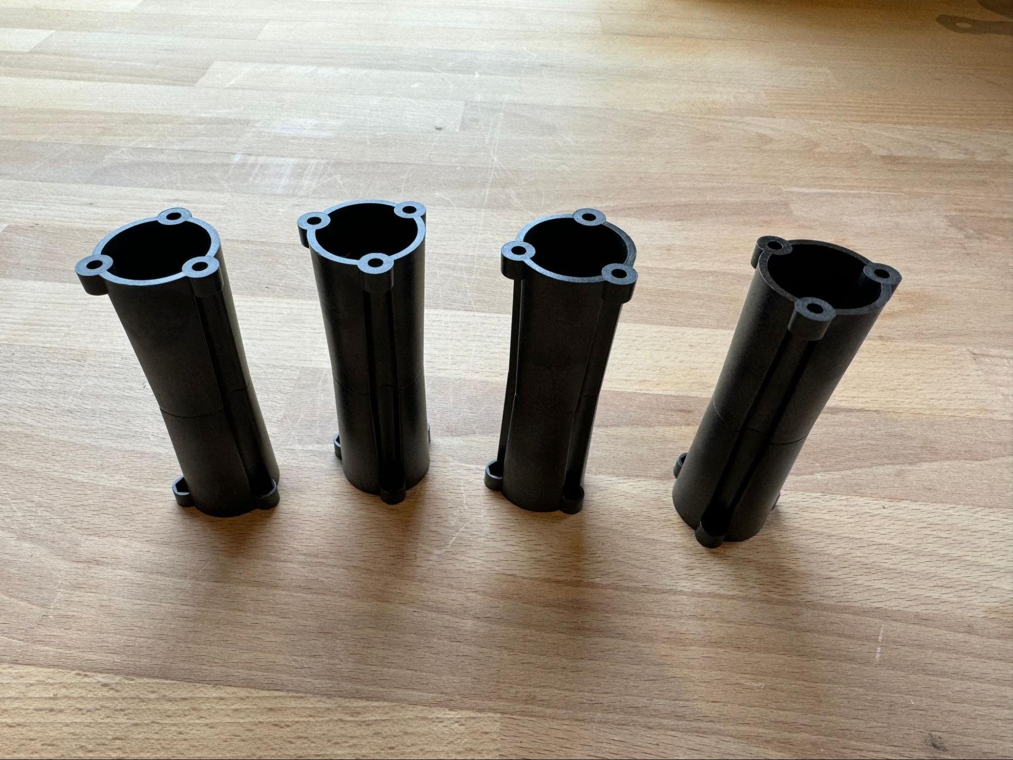
Repeat this step for all four uprights.
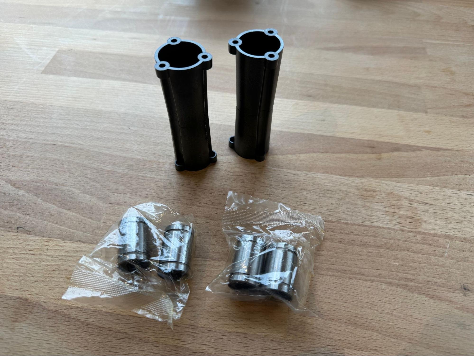
Next collect the linear bearings and two of the uprights.
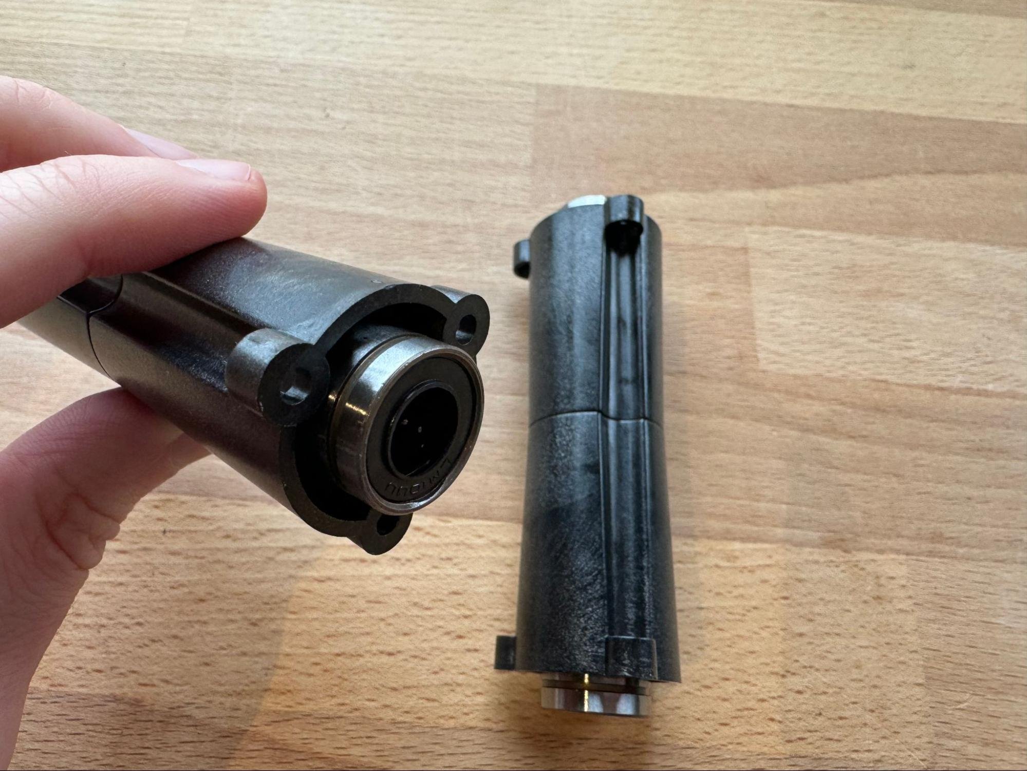
Press a linear bearing into each end of those two uprights.
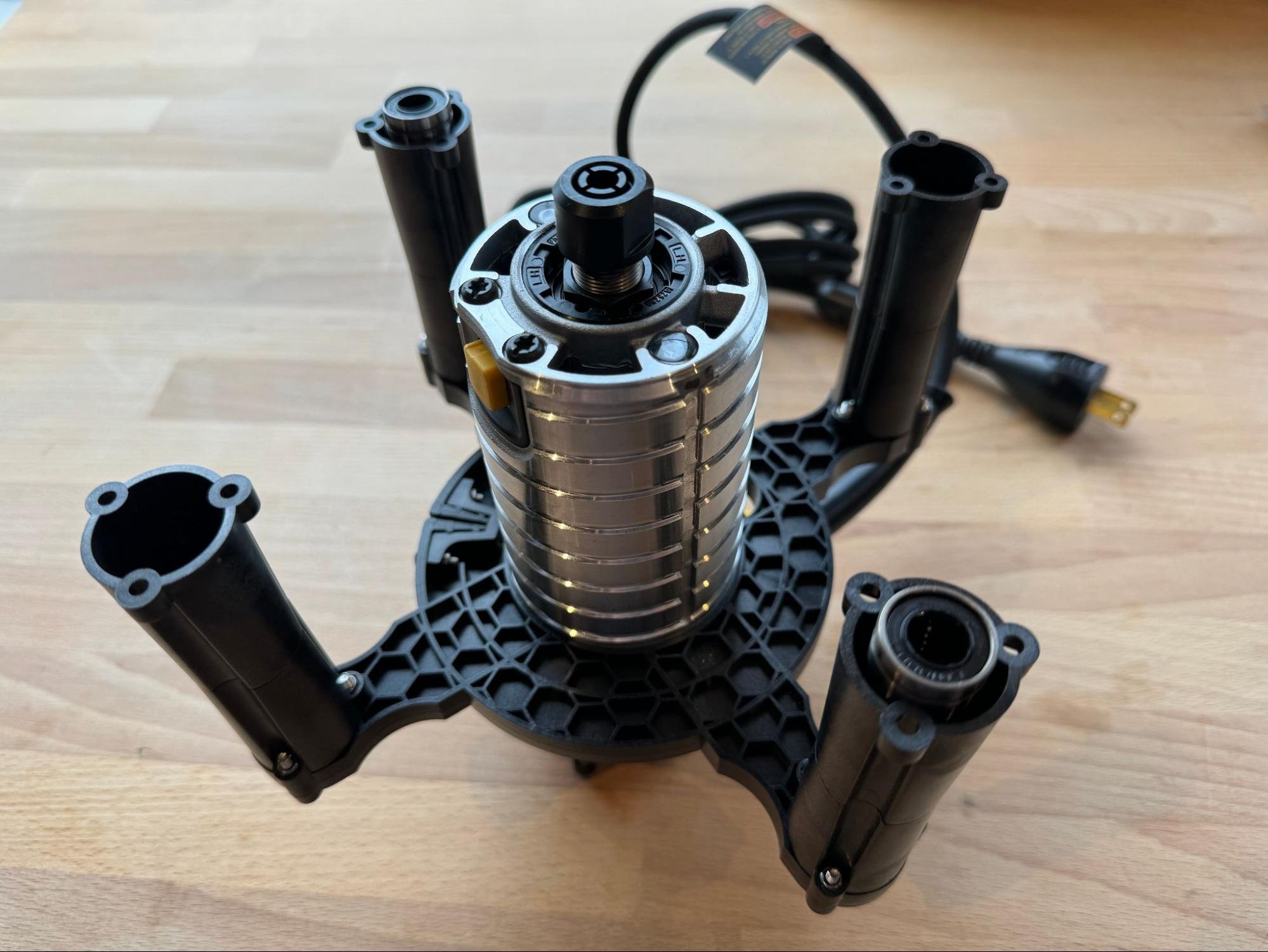
Next, we will bolt the uprights to the clamp. The uprights with the linear bearings will fit into recesses on two of the arms (shown on the right).
Note that the two uprights with the linear bearings go to the left and right of the power cord, while the two without linear bearings go close to the power cord and across from it.
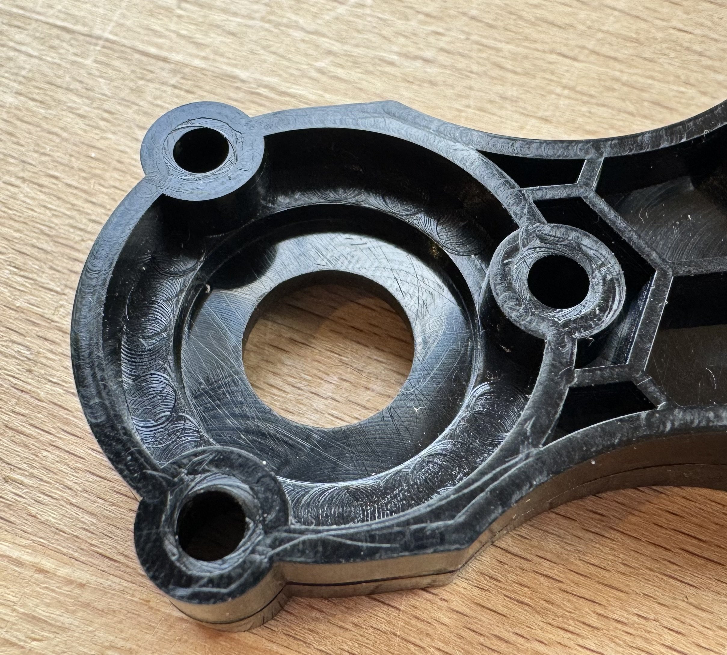
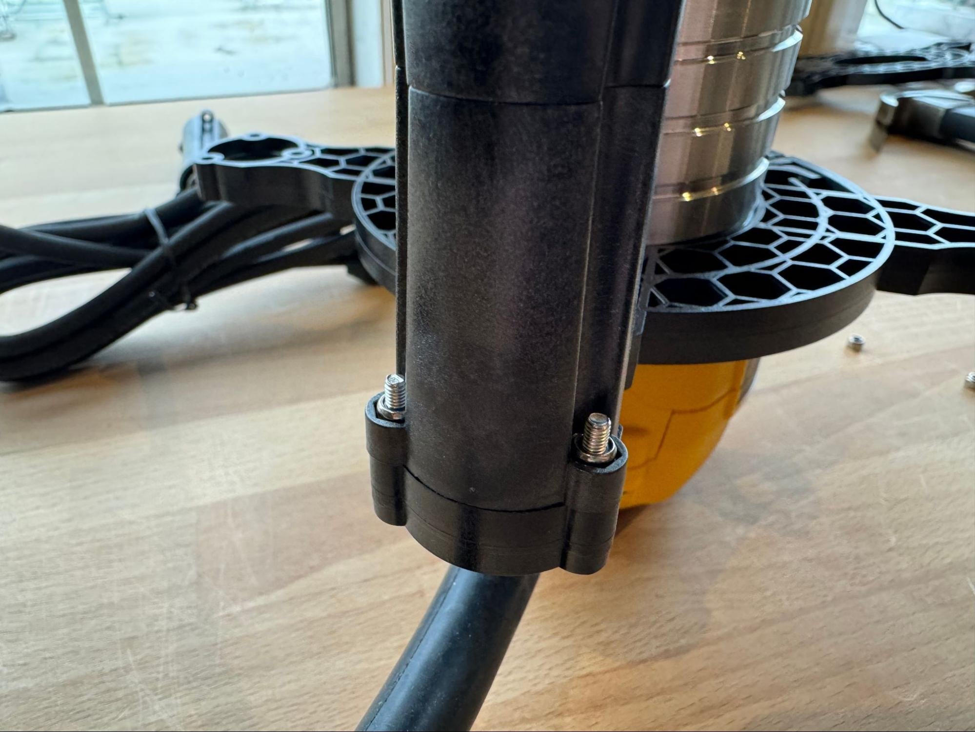
Each upright is held in place with three bolts.
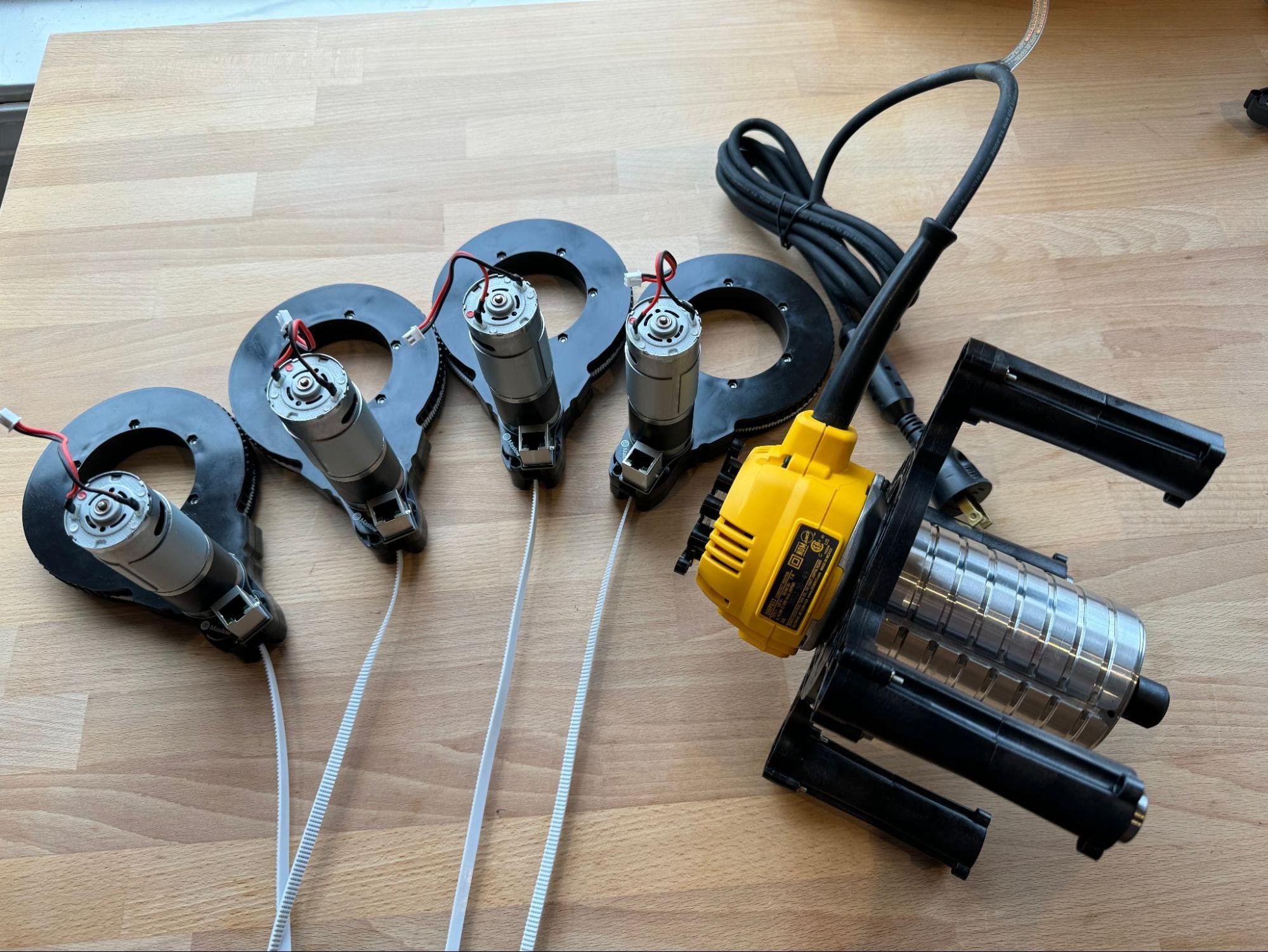
Gather the four arms that we built previously.
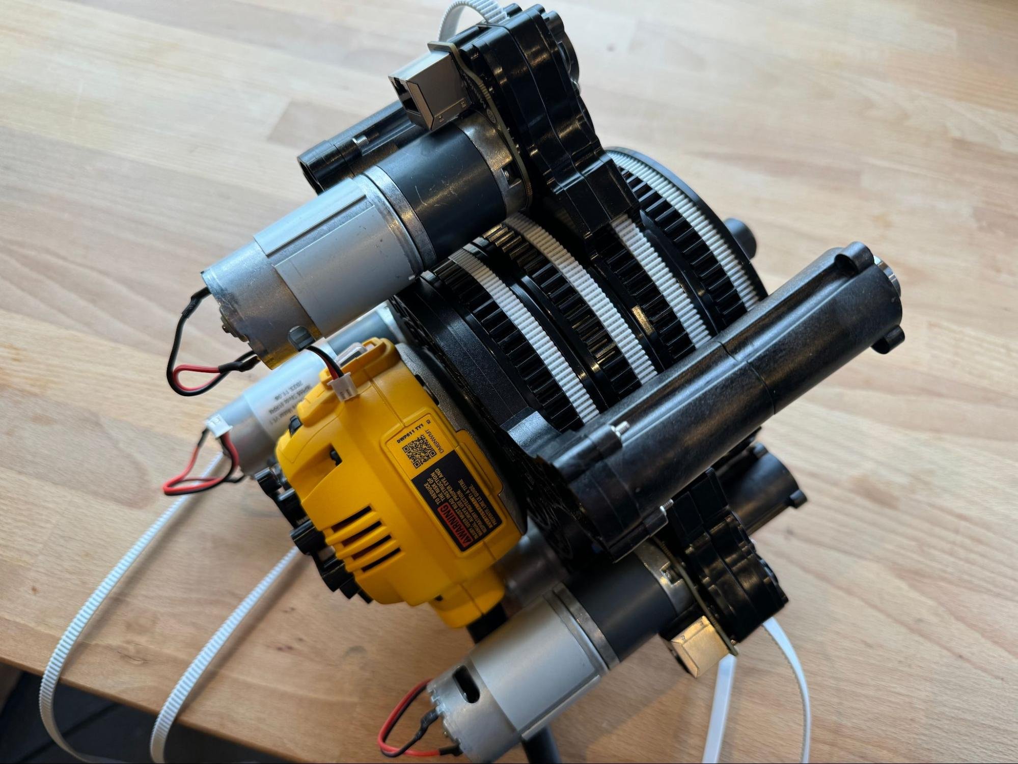
And slide them onto the router. Note that the order that they go on is important. See the illustration below for the correct order.
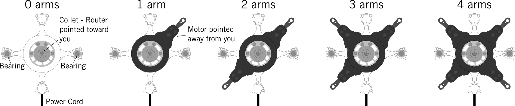
Credit to jwolter for creating this helpful image
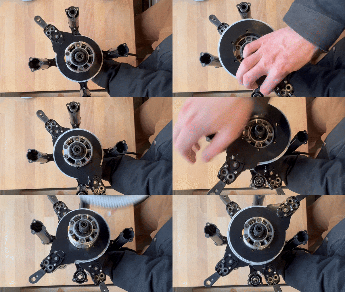
Here is a gif showing the assembly process. Note that the power cord is to the right in this clip.
And here is a video: Arm Installation Video
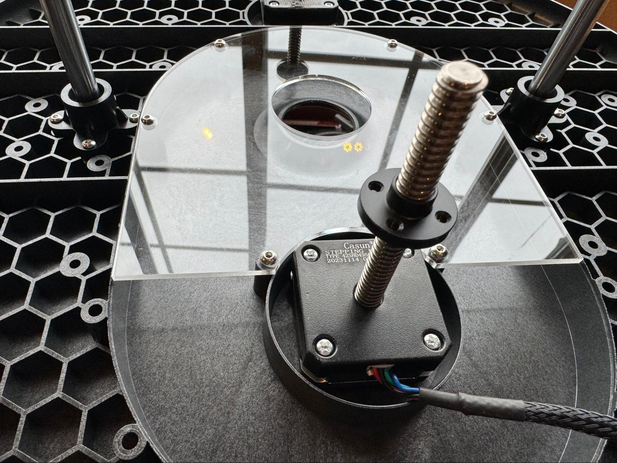
Next remove the two leadscrew nuts from the z-axis stepper motors attached to the sled.
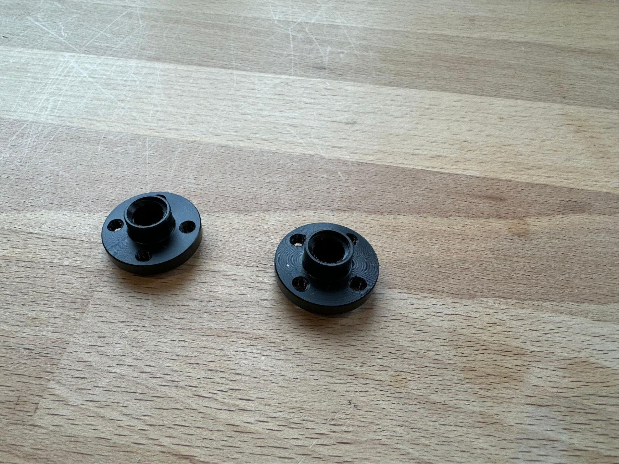
They will look like this.
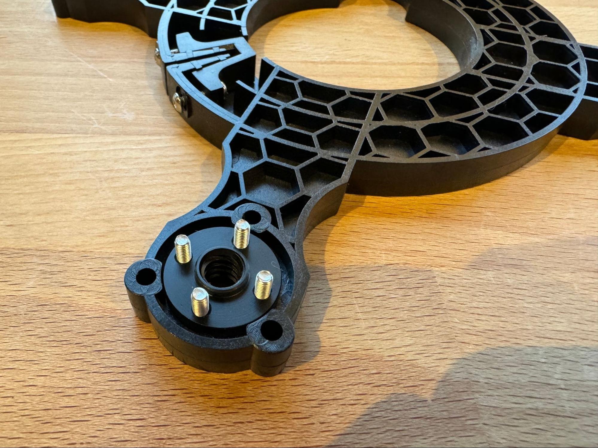
The two lead screw nuts will bolt into the second router clamp like this. The nut has a longer side and a shorter side. The direction is not critical, but I put the longer side down as shown in the picture.
Repeat the process of adding nuts and bolts to the clamping wedge on the lower clamp the same as on the upper router clamp.
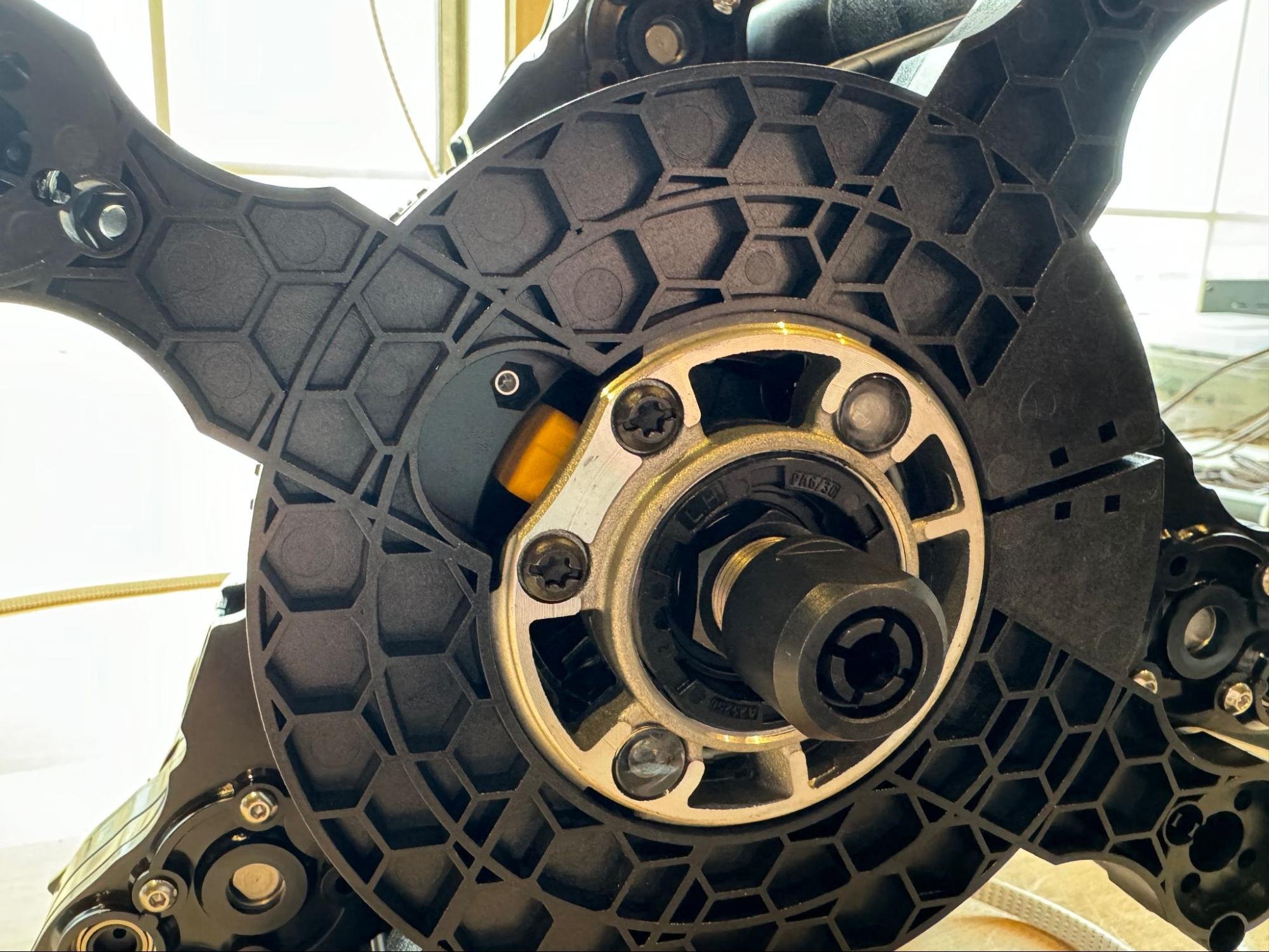
Flip the router clamp into place on the router so that the notch in the clamp aligns with the yellow button on the router.
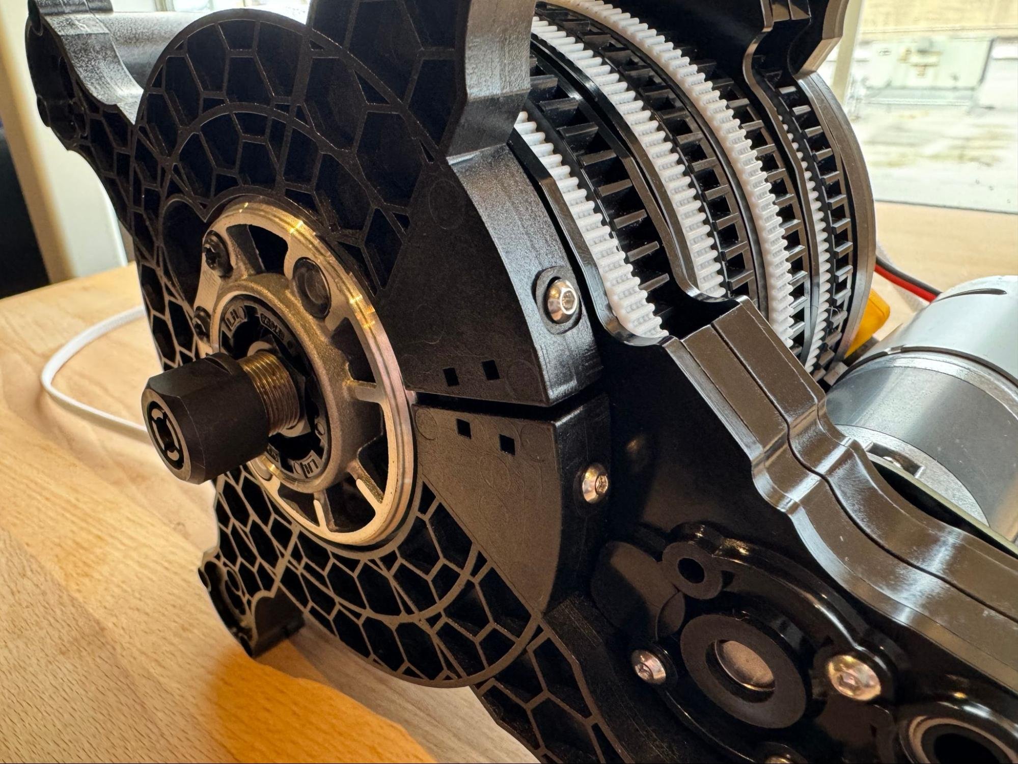
Tighten the bolts to lock the clamp in place
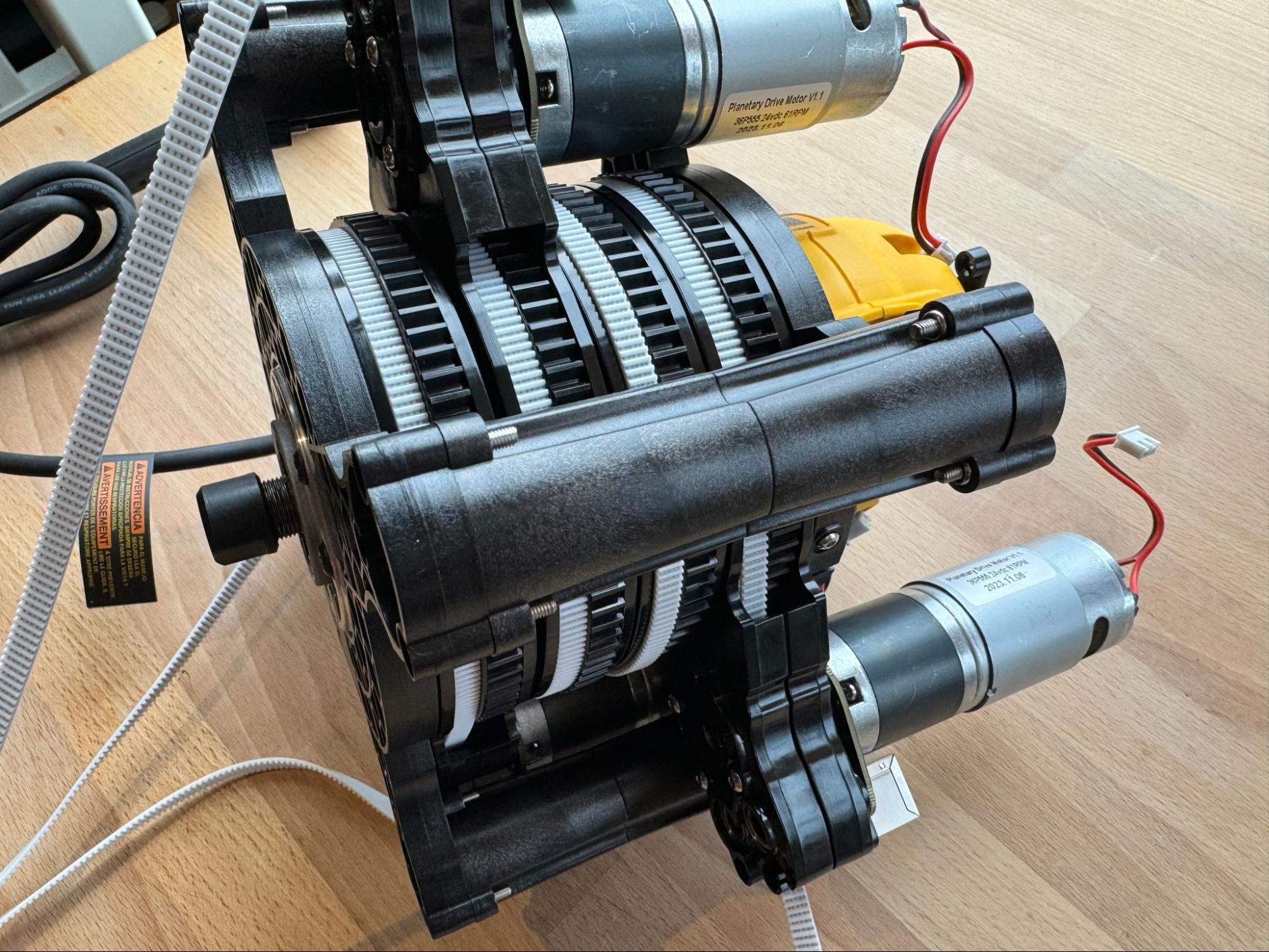
Then bolt it to the uprights like before.
Note: We recommend not using lock nuts in this step. If you need to take the machine apart you will remove this clamp and the lock nuts can be difficult to remove.
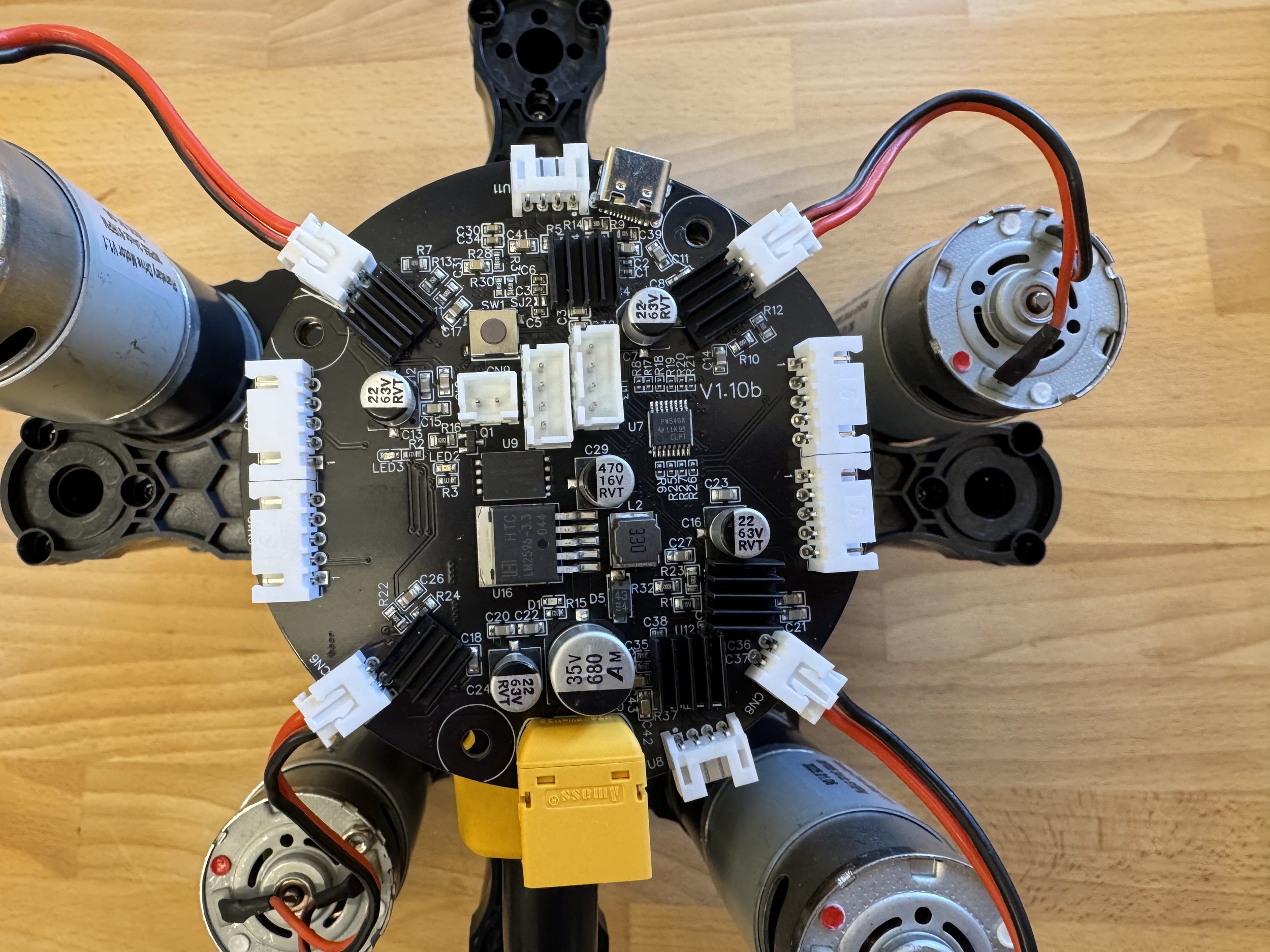
Place the main controller board on top of the router and plug in the four motors.
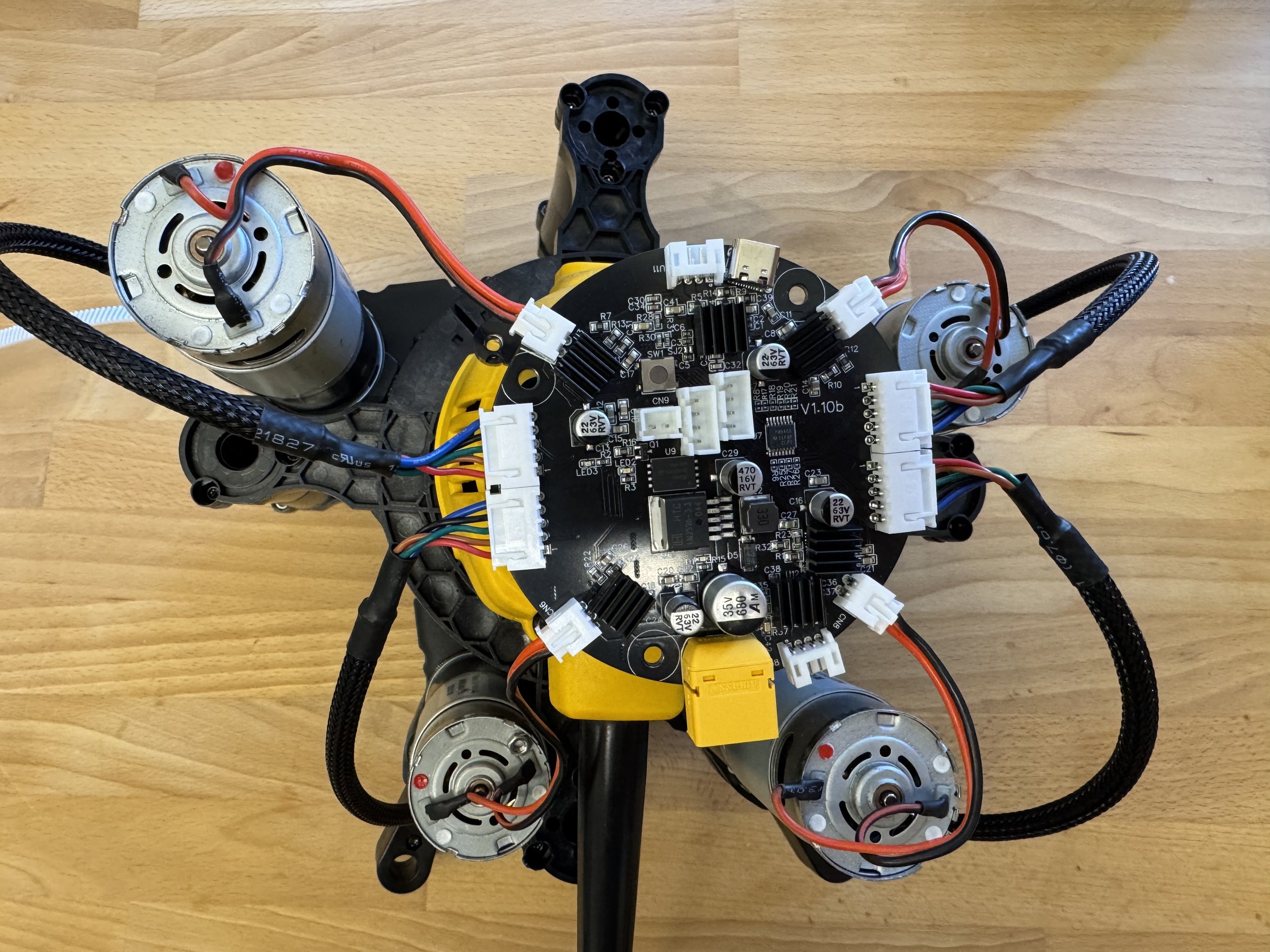
Use the four JST-XH cables to connect the encoders to the controller board.
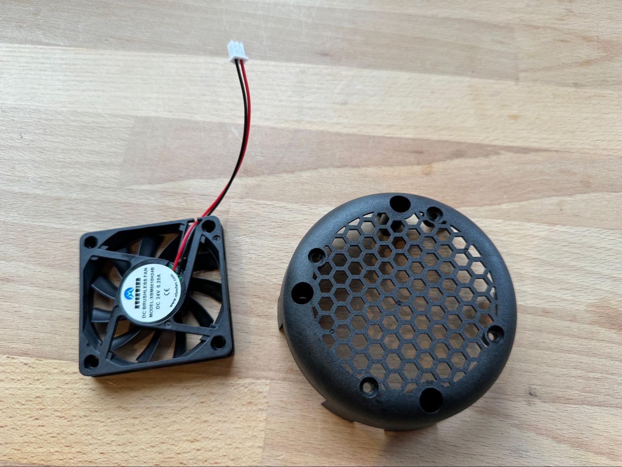
Next collect the cooling fan and the PCB cover
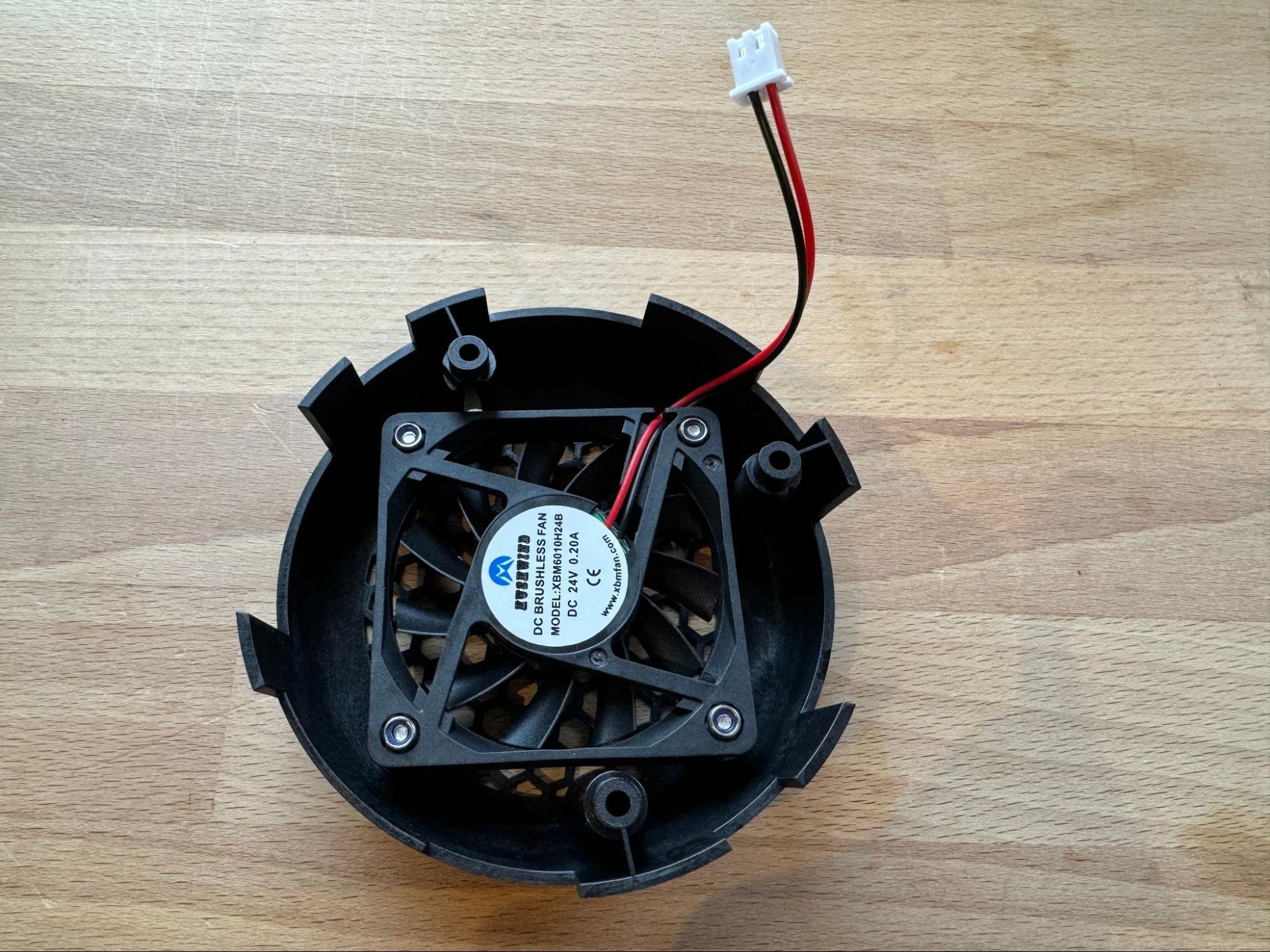
Bolt the cooling fan into the controller cover using four bolts.
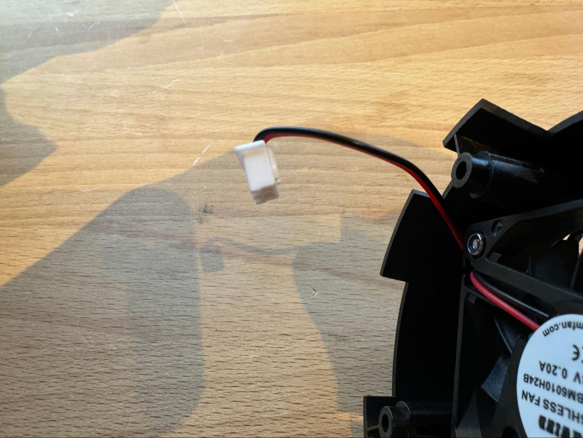
Add a slight bend to the fan wire close to the connector. This will help keep the wire directed so that it won’t go into the fan blades once everything is assembled.
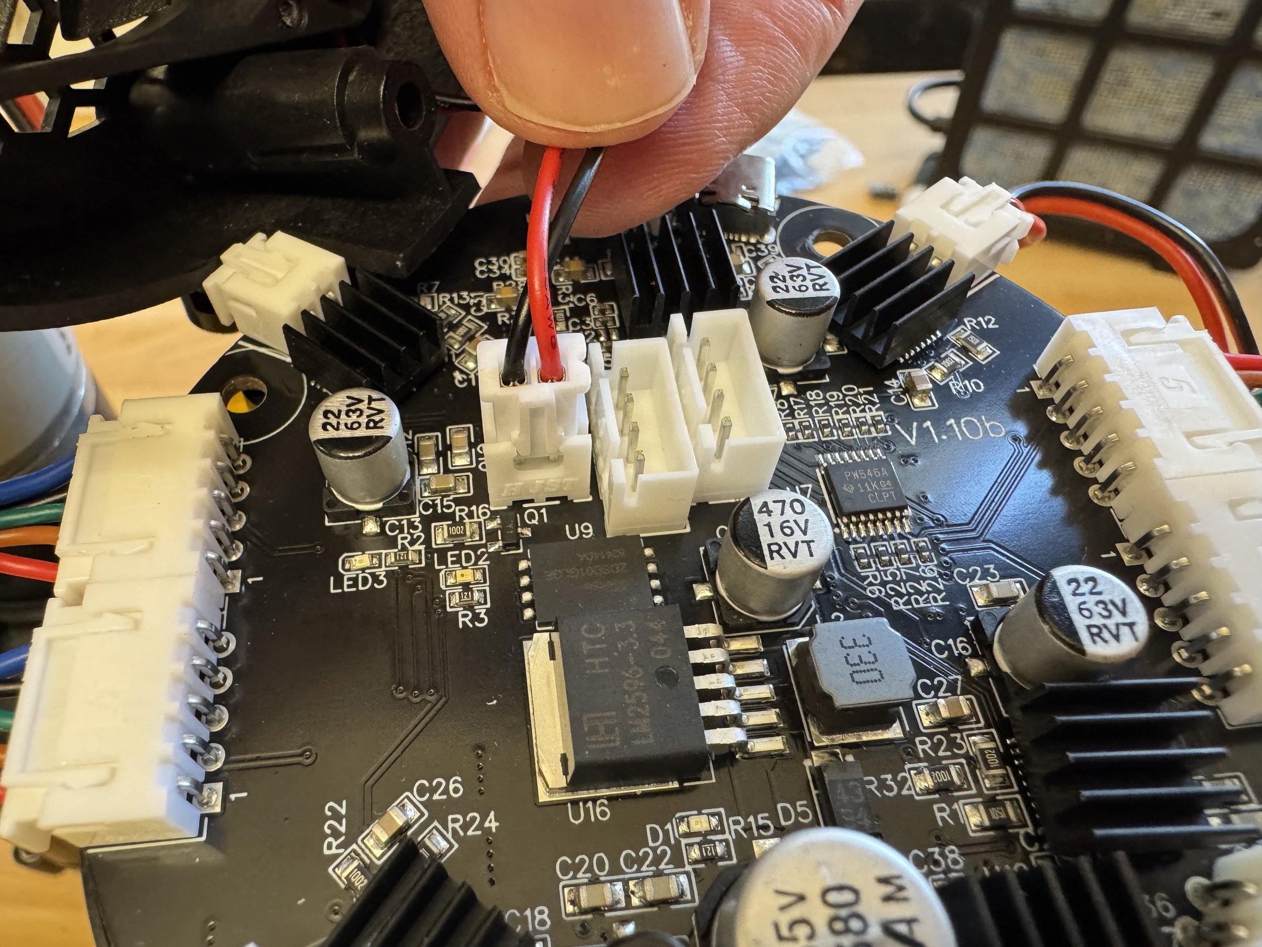
Plug the cooling fan into the controller board.
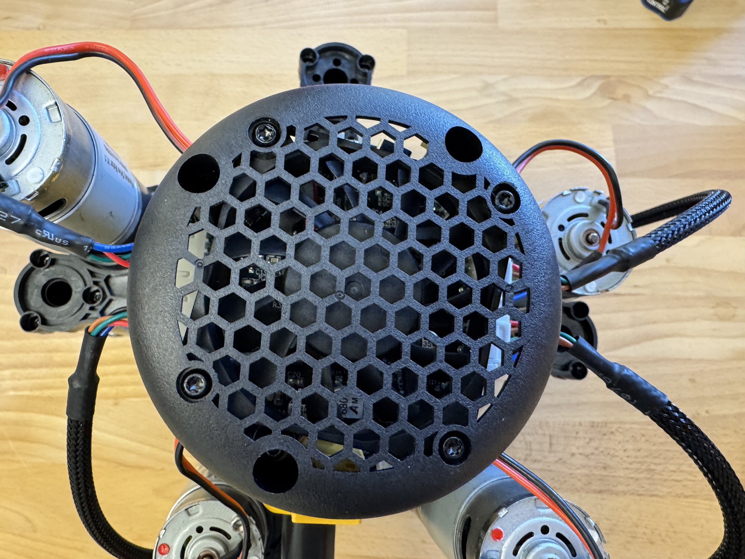
Finally bolt the PCB cover, the controller board and the router together using three bolts and three nuts placed underneath.
Congratulations! The heart of your machine is complete.
Next let’s put it all together.